control of mobile robots
After finishing my masters degree I realized that while I had spent a great deal of effort studying control theory for my thesis research, I knew very little about applying that knowledge to anything other than combustion. This led me to enroll in a 7 week online course called Control of Mobile Robots. This course was offered by Georgia Institute of Technology through the website Coursera. This was my first experience with doing any structured online learning.
I really enjoyed this course as it helped me shore up some of my basic control knowledge (that I didn't even realize I was lacking) while also teaching me some new interesting control solutions to problems in robotics that I had previously never thought about.
Course structure and programming assignments
The course had around 2 hours of video lectures that needed to be watched in order to pass the weekly mandatory quiz. However all the real learning for me was done in the weekly optional programming and simulation assignments. Every week in the programming and simulation assignments a differential drive robot was incrementally improved until it was able to successfully navigate through a concave environment and reach its end goal.
A differential drive robot is turned by sending a different speed to its left and right wheels (think of how a tank turns). Constantly thinking about the controller output in terms of left and right wheel velocities isn't very intuitive. The first programming and simulation assignment was to translate the dynamics of a differential drive robot into the more intuitive dynamics of a unicycle model. A unicycle model uses the angular velocity (turning left and right) and velocity (going forward and backward) instead of left and right wheel velocities.
Put an object on the ground a few feet in front of where you are standing. Walk towards the object, do a 180 degree turn around it, and walk back to where you were originally standing. Did you think about how you had to take small steps with your inside foot and large steps with your outside foot as you went around the object? No? Well that's because you are naturally thinking in terms of a unicycle model, not a differential drive. Our brain does this same conversion for us as we walk considering that our bipedal legs follow a differential drive model yet we think in terms of a unicycle model.
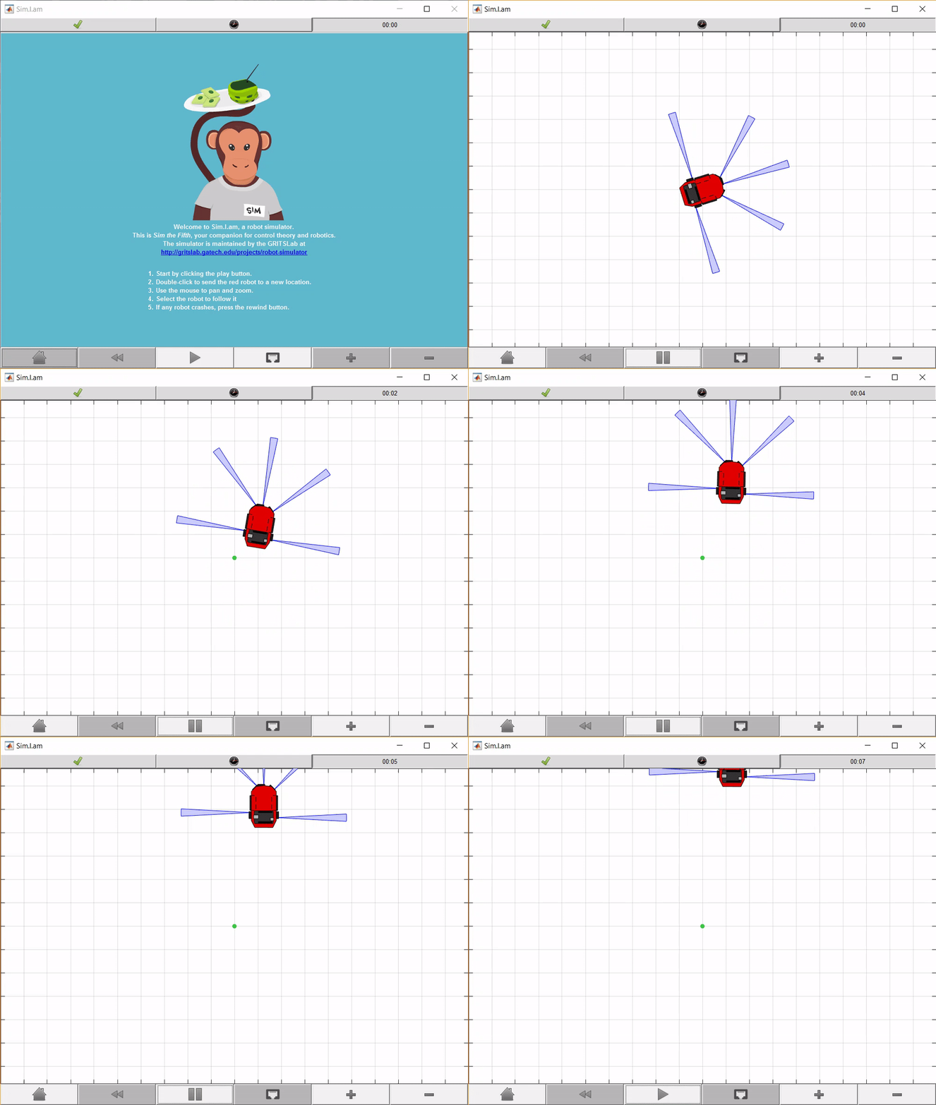
The results of using a P controller (regulating angle) on a unicycle model which is then translated into left and right wheel velocities is shown in the gif to the left.
PID and Obstacle avoidance
The next feature added to the robot was a PID controller which allowed the robot to have faster settling times when trying to reach a desired angle. In programming this PID controller I also had my first experience with the wonderful atan2 function that is found in most programming languages. On top of the PID regulator an extra control function was written that ensured that if the PID controller demanded maximum angular velocity when the robot was required to drive at its max forward velocity (something impossible with a differential drive robot) the robot would reduce its forward velocity in order to achieve the desired angle first.
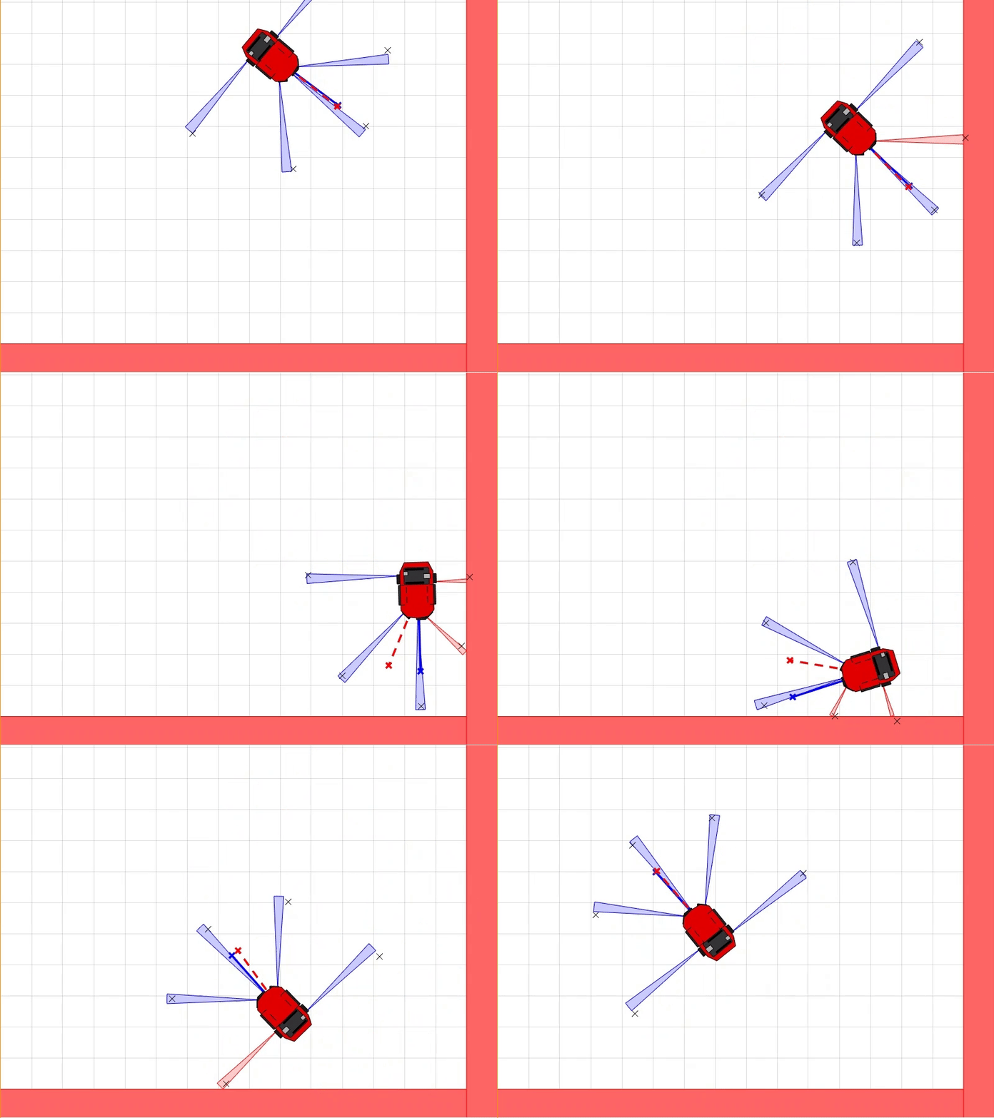
Using the 5 simulated IR sensors (shown in blue), an obstacle avoidance controller was created which operated by setting the PID reference (the angle the controller is trying to achieve, shown in dashed red) based on the sum of vectors created by the IR sensors.
For example, if all sensors are reading their maximum distance, the vectors on the left and right side of the robot will cancel out and the resulting vector will point forward. However if there is an obstacle directly to the right of the robot, the vectors produced by the IR sensors on the right of the robot will be much smaller than the vectors on the left. Thus the resulting sum of all vectors will be skewed to the robots left, steering it away from the obstacle. This controller can be seen in action in the gif to the left (the blue line is the robots estimated angle that is calculated using odometry on the left and right wheels).
follow wall
The follow wall control was accomplished by drawing a vector between the ends of two IR points (seen in the gif by the red line) and creating a reference angle for the PID regulator that is parallel to that vector. When the robot gets into the tight corner, you'll notice that that vector gets drawn between the middle IR sensor and the left sensor as it was programmed to create the vector between the two shortest IR points.
The distance from the robot to the wall is set by creating another vector that is from the robots center to the closest spot on the follow wall vector. By adding this vector with the follow wall vector (along with an offset that defines the distance from the wall the robot should try to maintain) a reference angle for the PID can be found. The follow wall control is seen in the gif to the left with the red showing the wall vector and the blue showing the vector pointing to the closest point from the robot to the red vector.
Putting it all together
The reason for developing the follow wall algorithm is that just using a mixture of driving straight at a goal (as in the first gif) and avoiding obstacles that might be in your way (as in the second gif) isn't enough to navigate complex environments. There are situations when the robot is trapped in an environment that it needs to escape before it can drive at the goal.
When the robot realizes that switching between a go to goal behavior and an avoid obstacle behavoir is not making progress (defined by the magnitude of the vector between the robot and the goal not decreasing), the robot will switch into follow wall mode (following the wall left or right is decided based on the direction of the follow wall vector, avoid obstacle vector, and goal vector) in order to escape the environment.
The robot will decide to leave follow wall mode once it has made progress (the vector from the robot to the goal is shorter than when it first entered follow wall mode) and the angle of the follow wall vector is no longer in between the angle of the go to goal vector and the obstacle avoidance vector. This second part reasons that the there is no longer a conflict between the goal vector and the avoid obstacle vector that follow wall vector can be used to resolve. This conflict can be seen when the robot is in the corner (very start of gif loop), the goal vector is telling robot to go to the top right and avoid obstacle is telling it to go bottom left. When this conflict doesn't exist the robot can exit follow wall and return to seeking the goal.


